
This tutorial will demonstrate how to use the XCS eiConsole to build an IRI (NAVA) compliant interface. 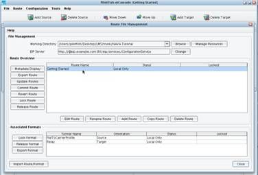 In this particular example you will be building a simple Interface from a Directory Flat File to an IRI (NAVA) compliant carrier profile message, also to be dropped in a Directory.
  Once you are done with this exercise you will be able to pick up a file that looks like this, containing basic rating information about a carrier…
 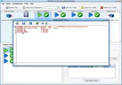 And translate it into an IRI (NAVA) compliant Carrier Profile message.
  Let’s get started. When you first launch the XCS eiConsole you’ll see the Route File Management window. The first thing that you will need to do is select the Working Directory in which you will build this interface. Select Browse to the right of Working Directory.
  Then Browse the local file system and create a New Folder for your work. Title it Carrier Profile.
 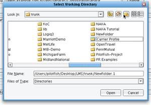 For the purposes of this exercise, you will also want to create two sub-directories in which you will drop and retrieve your files. Call these: drop and out.
  Then navigate in your Working Directory to find and select your newly created Carrier Profile Folder and click Open.
 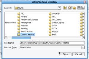 The eiConsole will prompt you to initialize this Directory as a proper XCS eiPlatform/XCS eiConsole Working Directory. Click Yes.
 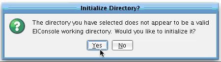 The Route overview grid will now be blank.
  The next thing to do is create an interface within the Working Directory. Select the Add Route button.
  Enter the name for your New Route: Getting Started. Click OK.
 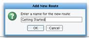 Your new Getting Started interface will now appear in the Route Grid. Double clicking this interface will allow you to begin to build out the Sources, Targets and Transformations required.
 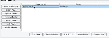 Once you click the Getting Started row in the main Route Grid, you will be presented with the main route screen.
  You will now define one Source System, which will be the source of the Carrier Profile data, and one Target System, which will be the recipient of that data. Click Add Source.
  Then click Add Target.
  Work from left to right through the flow of the interface configuring each stage in turn. First, click on the Listener icon in the main Route Grid.
 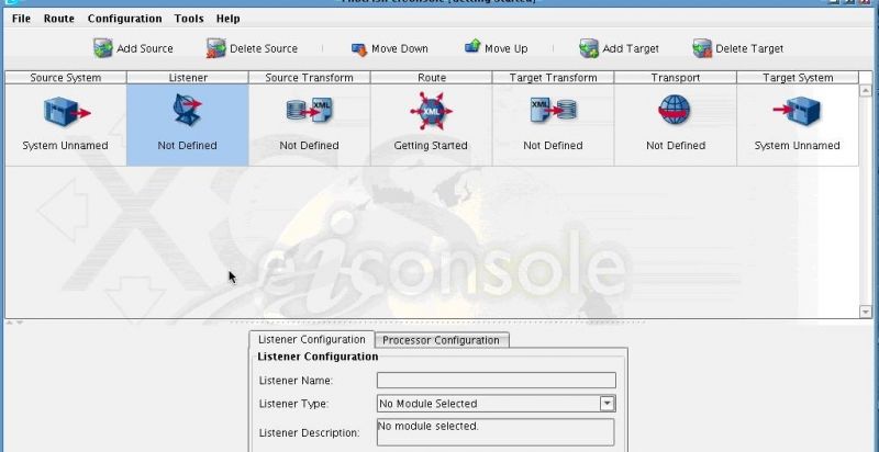 You will use a Directory Listener to pull flat file information from a Directory to be transformed into the IRI (NAVA) compliant Carrier Profile. From the Listener Configuration tab select Directory from the Listener Type drop-down.
  You will now be presented with a set of configuration panels that you will need to fill out. The red icon indicates a required field or a tab containing required information.
 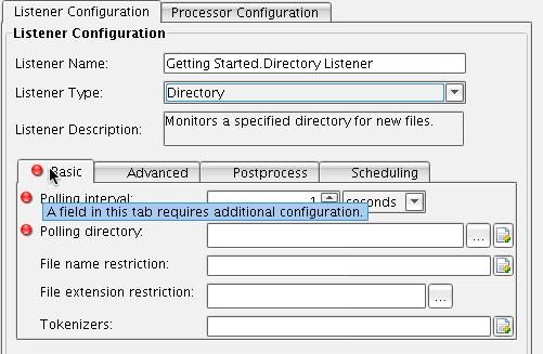 In this case, set the Polling interval to every 10 seconds.
  Next, choose to poll the input directory that you created. The … to the right of Polling Directory will allow you to select the correct directory. Click this button. Choose Carrier Profile and the drop folder. Then click Open.
  As the configuration items are filled in, the red circles will disappear indicating that you have successfully configured that item. Also choose to restrict the files that you pull from that directory to only those with a .dat extension. Enter dat in the File extension restriction configuration item. You have now completed configuration of the Listener.
  Now click on the Source Transformation icon. This will allow you to configure the transformation of the Source data, in this case a flat file, into your common format, which in this case will be the IRI (NAVA) compliant Carrier Profile message.
  Click Add Format to create a new Source Transformation.
  Provide the name: FlatFileToCarrierProfile. Enter the name and click OK.
 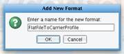 The recently created format will appear in the Format Profile drop-down.
  Now you will configure the appropriate Transformation Module and XSLT. Because your inbound data is a flat file, you first need to turn it into XML prior to data mapping. To accomplish this you will use the Delimited and Fixed-Width File Transformation Module.
 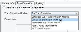 This Transformation Module is capable of taking Delimited or Fixed-Width data and converting it into an XML format. Essentially you are tagging this information so it can then be mapped using XSLT. In order to configure the Delimited and Fixed-With Transformation Module you will use the File Specification Editor. To launch the File Specification Editor, click the Edit button next to the File Spec configuration item.
 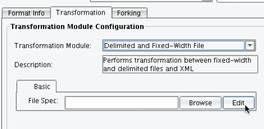 Clicking this button will launch the XCS File Specification Editor.
 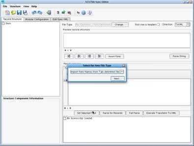 This is the tool that is used to describe the non-self describing Delimited and Fixed-With files that you will need to translate into an XML format. The File Specification Editor allows you to import descriptions from a variety of different formats, including DTCC record layout spreadsheets, also commonly used in tandem with IRI (NAVA) implementations.
  In this case, you will build your file specification from scratch. Select Other from the Select for New File Type dialog.
 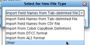 Select Next.
 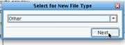 Now you will describe the layout of the file that you wish to process. In this case your records will be Delimited with new lines, so you will not need to change this item.
  However, the fields within each record will not be Delimited, they’ll be Fixed With. Select the radio button Fixed Width and click Save.
 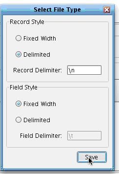 You will now be presented with an empty XCS File Specification.
  The first thing to do is load a sample file for reference. Click the Open icon in the Results preview section.
 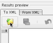 Select the file ratings.dat included in the docs folder underneath this tutorial.
 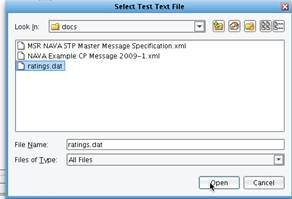 When you click Open, you will see the sample file. In this case, the sample file includes three different types of records.
 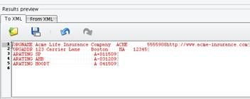 There is an ORGNAME record that includes information including the name of the organization. You will have an ORGADDR record that includes information about the address where the organization is located. Then there is a repeating set of ARATING records representing ratings that were provided by a rating entity.
 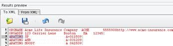 Your next step is to define this layout in the tree on the left hand side of the screen. You will need to create three records to represent the three record types found in this file. To do that, select the root node. are nodes which have attributes and child nodes. generally they pretty interchangeable. using a good analogy you can think of it this way: node is like fruit an element apple. apple kind class=”lexicon-term”>node of the tree, right click, and choose Add New Record.
 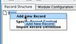 Do this three times for each of the record types that you will be parsing: Name Record, Address Record, and Rating Record.
 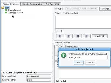 As a next step, you will want to associate the appropriate lines of the file with each one of the record definitions. First, click Name Record in the tree on the left. Then highlight the Name Record in the Results preview window from the sample file, and choose Set Selected Text.
 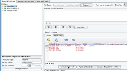 You can preview the record structure in the box at the top.
  Do the same for the Address Record and Rating Record. Now, any time that you work with any of these records, the appropriate sample data will show up in the Preview record structure window. The next step in the process is to define the fields underneath each one of these records. Start with the Name Record. The Name Record contains a record type, the name of the insurance company, the company symbol, a code, a group code, and a website. For each, right click on NameRecord and choose to Add New Field.
  Provide a name for the field and click OK.
 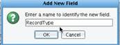 Once you have done that, a new blue Node will appear in the File Specification tree.
 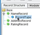 You will also see blue icons within the Preview record structure window that can be used to define the bounds of that field.
  First, define the record type. Select the blue arrow to the right hand side in the Preview record structure tree, and drag it to the bounds of that record type, which is right before the beginning of the carrier name.
 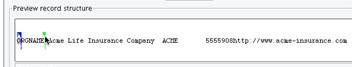 Repeat this process for the other fields in the Name Record: Select NameRecord, Add Field Name, drag the corresponding arrows to correctly define the field where code is 4 digits and group code is 3 digits.
 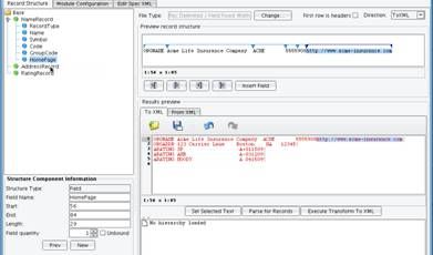 Do the same for AddressRecord: Add Record Type, Address, City, State, and Zip.
  Do the same for RatingRecord: Add RecordType, RatingEntity, Grade (rating provided by that entity), and Date (when rating was issued).
  You have now successfully defined the bounds of all of the fields under each of the record types.
 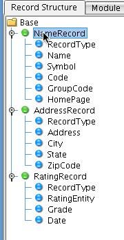 The next step is to define a record control; that is the logic used to determine what record you’re parsing at a particular point in the file. To do this, click on Base within the record structure and then choose Specify Record Control from the right-click context menu.
  Choose to define a new record control.
 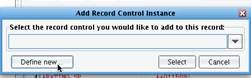 Select the Field RecordControl option from the Record Control Type dropdown. Then choose Add RecordControl.
 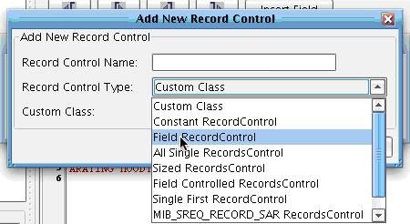 Next choose Select.
 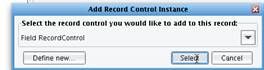 A red node will now appear in the tree.
 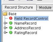 A field based record control uses some content within each record to determine what record type you will be parsing. In this particular file format, the first seven characters of each line represent the record type. You can encapsulate that logic by configuring the Field Record Control. Select the field record control configuration below, click on the Control Fields node within the Configuration tree, and select Add from the context menu.
  Name this field Record Type, and define it as the first seven bytes of this line.
  You will now use this record type field that you’ve defined and add conditional logic to determine what record type to process based on the content of that field. To do this, left click on the Control Cases node in the configuration tree. Right-click to add a Control Case.
  You will need to create three Control Cases, one for each record type. In each case the Test field will be RecordType. The value will differ based on the first seven bytes that you expect. 1. In the first case, the value is ORGNAME and you will use the record called NameRecord. Enter the values and click OK.
 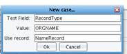 You now need to repeat this process for the Address and Rating records. 2. Click on Control Cases, right click to Add a case, enter in the Test Field of Record Type, the value of ORGADDR, and the record AddressRecord.
 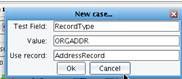 3. The final case will be for the repeating RatingRecords. Add a Control Case, with RecordType as the test field, the expected value of ARATING, and the corresponding record of RatingRecord.
  You have now successfully defined the Record Control Configuration. You can now validate that the definition you’ve built is in fact correct. Click the Execute Transform to XML button in the lowe-right hand side of the screen.
 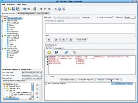 When you do that, the tool will parse the loaded sample file into its corresponding records. You’ll see that it completed successfully, generating a NameRecord, AddressRecord, and three RatingRecords.
  You have now completed the File Specification and can move on to the next step of the process. First, save your File Specification. Choose the save icon.
 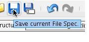 Give it the name RatingFlatFile-Spec and choose OK.
 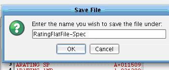 You can now click the door icon to return to the eiConsole main screen.
 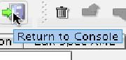 You will see that the output of that process was an XML file now being used as the configuration of the Delimited and Fixed-Width File Transformation Module.
 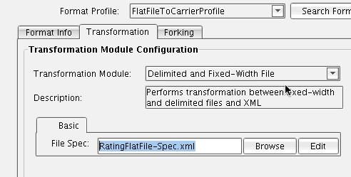 Your next step is to create the Data Mapping from the XMLized version of your flat file into the IRI (NAVA) carrier profile message. To do this, you will use XSLT generated by the XCS Data Mapper. To generate the XSLT, uncheck the Use Direct Relay box.
 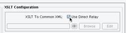 Then click Edit to launch the Data Mapper.
  The XCS Data Mapper is the tool offered in the XCS eiConsole that allows you to logically map data between an arbitrary Source format and a Target format. When you use this tool you first need to load in the desired Source format as well as your desired Target format and then you drag and drop to create the mapping in the middle.
 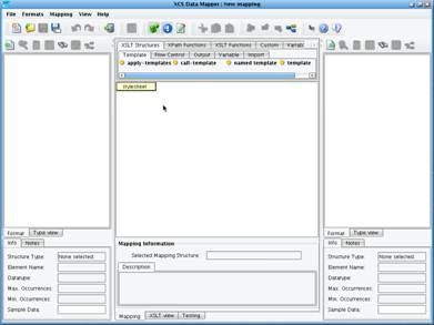 In this case, the Source format will be the File Specification that you just defined. Click the Open Source Format icon above the left hand panel.
  The Select Format dialogue box will appear. Choose the Flat File format builder to indicate that you will be reading in this format from a flat file specification developed in the File Specification Editor. The Flat file Format Files dialogue will appear.
  Click Add to specify the format that you expect as input.
 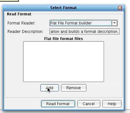 In the Carrier Profile working directory that you just created there will be a Formats folder, under which you will see a FlatFileToCarrierProfile subfolder. Inside this you will find the RatingFlatFile-Spec that you just defined. Select this in the file dialogue and choose Open.
 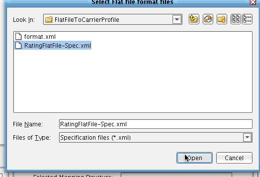 The name of the file will appear in the configuration panel. Now click Read Format.
 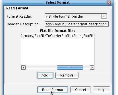 Having done this, you will now see a tree of blue node. are Nodes which have attributes and child nodes. generally they pretty interchangeable. using a good analogy you can think of it this way: node is like fruit an element apple. apple kind class=”lexicon-term”>nodes on the left hand side of the screen, directly reflecting the format that you just built in the prior tool. This will be your Source structure.
 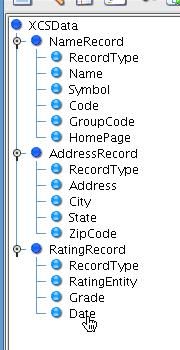 Now that you’ve loaded the Source format from the File Specification on the left hand side of the tree, you will need to load the IRI (NAVA) message format on the right hand side of the tree. To do that, click the Open Format icon above the Target tree.
  This will, again, launch the Select Format dialo. Note that the XCS Data Mapper supports a wide variety of input formats including XML schema, Flat File formats, sample XML files, HTML forms, WSDLs, and databases. It also has special support for several insurance specific formats. These include the ACORD schemas, the DTCC record layouts, and the IRI (NAVA) specification. Select that IRI (NAVA) specification using the IRI (NAVA) format builder. Choose Read Format.
 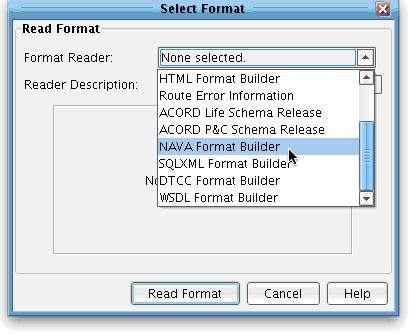 When you do this, you will then be prompted to provide the IRI (NAVA) Master Message XML file. This XML file, provided as part of the IRI (NAVA) deliverables, contains useful documentation, typecode information, and message specific validation rules much richer than what can be found in a traditional XML schema alone. To select this file, click Browse.
 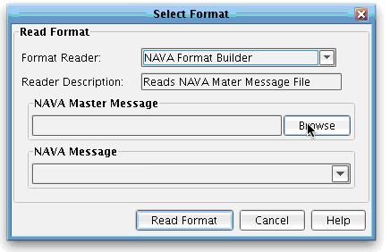 This file is provided as part of the IRI (NAVA) standard deliverable, but is also made available as part of the tutorial directory include with your download. In the docs folder, you will see the master message specification XML file. Select it and click Open.
 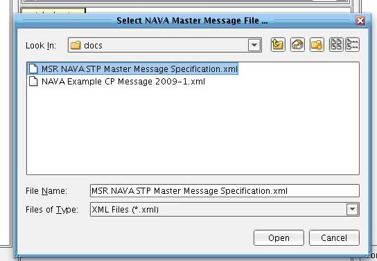 Once a Master Message specification has been selected and loaded successfully, you will see an IRI (NAVA) message dropdown. This dropdown is dynamically populated with all of the messages available and defined in the loaded version of the IRI (NAVA) specification. Each message has its own schema, documentation, and validation rules. In this case you will be using the IRI (NAVA) Carrier Profile. Select this from the IRI (NAVA) message dropdown.
  Then choose Read Format.
 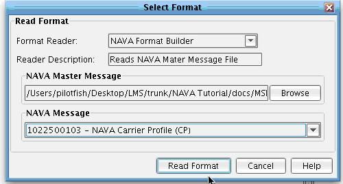 The schema for the IRI (NAVA) carrier profile will be loaded in the right hand side of the tree. You’ll also see, as you navigate various nodes in the Target tree, that all of the associated IRI (NAVA) documentation for each field, as well as any conditional rules associated with an element, are present below the associated tree.
 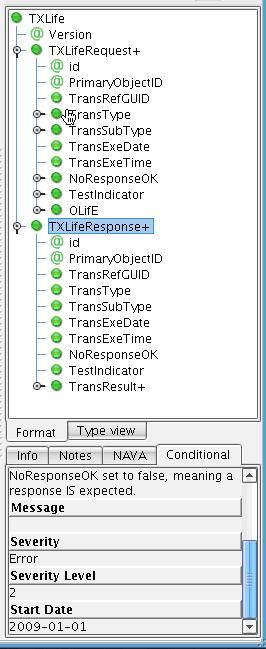 If you click on an element that uses a typecode, you’ll notice that a codes tab also appears including the allowed codes for this particular field. For instance, the carrier profile requires a 1204 trans type as well as a 1022500103 TransSubType.
  This documentation can be used to determine what fields you should map to as you create your carrier profile, or any other IRI (NAVA) message. Note that the elements shown in this tree are only those used by the particular IRI (NAVA) message in question. The next step is to load in the template of the message that you would like to create. To do this, on the right, click the View Sample Data icon above the Target Tree.
 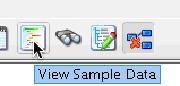 Then select the Open icon. Select the sample XML file representative of what you want to create. A sample CarrierProfile message is available in your IRI (NAVA) tutorial directory under the docs folder with the name IRI (NAVA) Example CP Message 2009. Choose this document and select Open.
  The contents of this sample message will now appear in your Target format sample data dialog. This is the general structure that you will want to use when creating the carrier profile message. Click Close.
 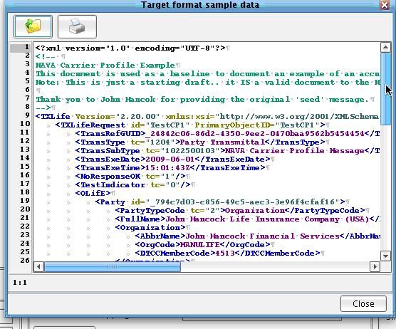 You will now want to pre-populate the middle of the mapping with the structure in that sample file. To do that, under the Formats menu, choose Add Target Sample Data As Template.
  You will be asked if you want to load values from the sample to the mapping. In many cases you won’t want to use many of the sample values; however, they can be useful in determining how the data should look. Click Yes.
 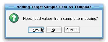 The middle mapping window is now populated by a number of green nodes. These green nodes are XML elements that are present in the result and represent the general structure of the CarrierProfile message that you will be creating. If you were to run this transformation right now it would simply generate the sample message that you previously loaded into the view sample Target window.
  Your job now is to replace the static values in the sample that you want to map from your Source. Let’s work from top to bottom through the map doing just that. Keep the TXLife and TXLifeRequest sections as is. For the purpose of the demonstration, we won’t dynamically generate a TransRegGUID. The TransType will always be 1204 and the TransSubType will always be 1022500103. Let’s dynamically populate the TransExeDate and TransExeTime. To do this, select the text node underneath TransExeDate, right-click, and Delete.
 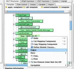 Do the same for TransExeTime.
  You’ll want to map these values not from something in the left hand tree, but instead, dynamically from the current date and time. To do that, click the Custom tab in the pallete above the mapping.
 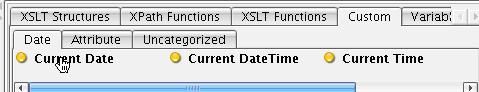 Then drag Current Date on top of the TransExeDate element.
  Do the same for Current Time on the TransExeTime element.
 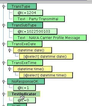 Leave the NoResponse and TestIndicator elements hard coded as is. Do the same with the Partyid and PartyTypeCode. Scroll down to FullName, the first value that you will dynamically map. You’ll take FullName from the Name field underneath the in NameRecord of the Source. To do this, remove the existing hard coded mapping by selecting the text element, opening the context menu by right clicking, and then selecting Delete.
  Replace that with the Name element by selecting the Name element from the Source, underneath the NameRecord, and dragging it on top of the FullName element in your mapping.
  You’ll see that FullName now has a blue child, NameRecord/Name indicating that you want to take the name field underneath the NameRecord and use that to populate FullName in the map. Repeat this process to map the same field to AbbrName under Organization in the mapping. You’ll note that as you add elements to the map, checkmarks will appear indicating an element that you mapped already.
  Continue this process to map several more fields. OrgCode will be mapped to Symbol. DTCCMemberCode will be mapped to Code.
 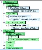 In the address section, our sample didn’t include Line1 data, but we have it. Map it to the address field underneath AddressRecord. The ACORD/IRI (NAVA) City element will be populated with the City element underneath the AddressRecord. Similarly, Zip will be populated with ZipCode from the Source.
  AddressStateTC is a slightly different scenario. Here you’re not doing a straightforward mapping from the value in the Source into the AddressState typecode element. Instead, you need to do a tabular mapping between your inbound value, a 2 character code, and the IRI (NAVA)-permitted typecode values. Begin by deleting the text element underneath AddressStateTC: Text=MA.
 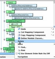 Map the State element from AddressRecord in the Source on top of the AddressStateTC element in the mapping. If you left this as is, the value of the inbound State would be used to directly populate the TC attribute, which is incorrect. Instead you’ll need to create a tabular mapping. To do this, select the Uncategorized sub-tab underneath the Custom tab in the Data Mapper. Choose the Tabular Mapping tool.
  Drag it onto the TC attribute. Click Define new.
 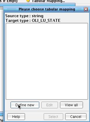 Provide a name for the mapping. Call it StateMapping. Note that the Target values in the tree are populated with those ACORD typecodes that IRI (NAVA) allows for this particular usage within the specification. Then map the values from the source system onto these. For instance, MA for Massachusetts (type this directly into the Box to the left of Massachusetts under the Source Values column). Add CT for Connecticut and CA for California, etc. Then hit OK.
  Select the Map.
  You will now see a new yellow node in the map indicating that you will be using this TabularMapping to map the inbound State code to ACORD/IRI (NAVA) allowed Typecode value.
  Let’s continue through the mapping. Let’s assume that our AddressCountry is always in the US, leave this as is. In the Carrier section, we’ll map CarrierCode to the Code underneath the NameRecord from the Source. Do the same with the NAICCode. Map GroupCode to the inbound GroupCode element.
 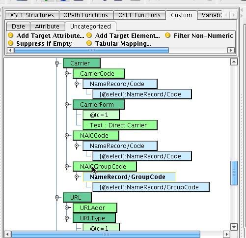 In the URL section you will replace the existing URLAddr with the HomePage from the NameRecord.
  The URLType can remain hard coded. You’ll now see that the sample has several different Rating Agency Information sections (RatingAgencyInfo). You’ll want to create one of these sections for each rating record that you encounter. To do this, you’ll want to add an XSL for-each structure to your mapping. Select XSLT Structures in the pallet above the mapping and choose the Flow Control sub-tab.
  Select the for-each tool and drag it directly above the RatingAgencyInfo section. It should appear at the same level of the tree as the RatingAgencyInfo.
 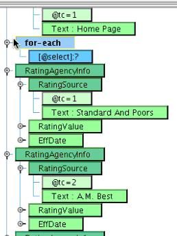 You will want to do this for each RatingRecord. To accomplish this, now take the RatingRecord from the Source and drag it on top of the for-each. This means that during mapping you’ll generate anything that falls underneath the for-each for each RatingRecord that you encounter.
 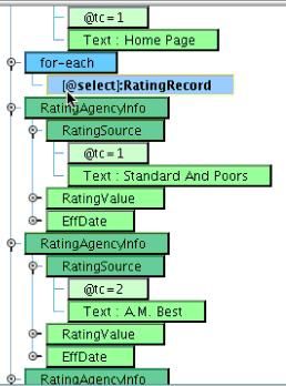 You will now need to move the RatingAgencyInfo underneath this for-each block. To do this, select the RatingAgencyInfo element and drag it on top of the for-each element. It now becomes a child of the for-each.
  You’ll note that you now have several redundant RatingAgencyInfo sections. You will need to delete these. Left click on each to select, then open the Context Menu and Delete the other two RatingAgencyInfo elements.
 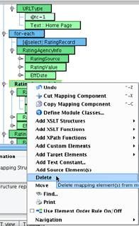 You will now have three elements that you need to populate: RatingSource, RatingValue, and EffDate. These will map to the RatingEntity, Grade, and Date, respectively. First map the RatingSource. Delete the hard coded text value of Standard and Poors and map RatingEntity onto the tc attribute of the RatingSource. Much like with the AddressState, this requires a typecode mapping.
  Return to the Custom tab, choose the Uncategorized sub tab, and drag the Tabular Mapping tool on top of the tc attribute. Click define new.
  Name this map RatingEntityMap and enter in values for each of the allowed IRI (NAVA) values. Standard & Poors will be represented in our file as SP, A.M. Best will be AMB, Moody’s will be MOODY, Fitch will be FITCH, and Weiss Ratings will be WEISS. Enter these values and select OK.
  Then Select the reusable tabular mapping that you just created. Your tabular mapping will now appear in the center panel.
  The RatingValue element will be mapped one-to-one to the inbound Grade. Delete the value of Text:AA+. Drop Grade on top of RatingValue.
 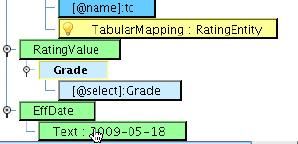 EffDate will be mapped to Date. Delete Text: 2009-050-18 and drop the Date element from the Source onto EffDate. However, your inbound Date is not formatted the same way that IRI (NAVA) expects EffDate to be formatted. If you recall, your sam ple data formatted dates in one format with no punctuation. IRI (NAVA) expects this same information in a different format. To do this conversion, use the DateTime converter available underneath the Date subtab of the Custom tab.
  Drag the Date/Time Formatter onto the Date field. The Date formatting dialogue will appear. Enter the expected input pattern of ddMMyy and output of yyyy-MM-dd and then select OK.
 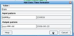 All of the required mapping logic is created underneath the EffDate element.
  You have now completed your logical mapping and can save the XSLT and continue to work on your interface. Click the disk icon.
 ![]()
![]() Provide a name for the XSLT that you just created: FlatFileToCarrierProfile.
Provide a name for the XSLT that you just created: FlatFileToCarrierProfile. 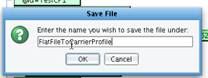 Then click the close icon to return to the Console.
 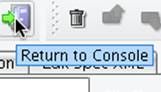 Now continue configuring the topology of the interface. The Routing stage allows you to associate metadata with the interface or provide Routing Rules should you have defined multiple targets. You didn’t do any of that in this interface so no configuration is required.
  NAVA127 Transaction Monitoring allows you to specify how the interface should behave if something goes wrong. Such exception handling isn’t required in your sample, so you’ll just continue on to the Target Transformation.
  This particular interface only requires a one-sided transformation. You won’t be transforming the data from the carrier profile into any other data formats, and that is the typical use of a TargetTransform.
  When you just want to send the data along without any further manipulation you will create what is called a Relay Transform that does no work with the data as it flows through this stage. To create the Relay Transform, click the Add Format button…
 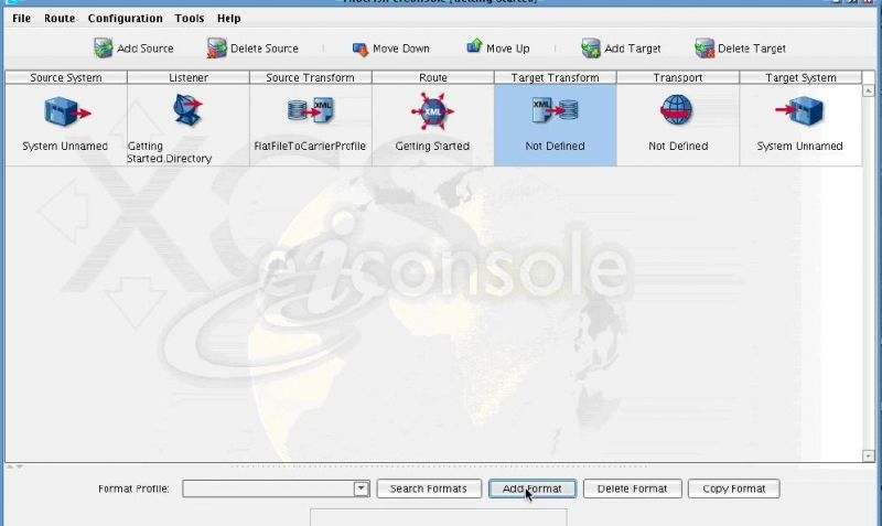 And provide the name Relay.
 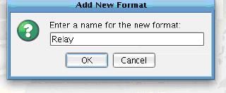 You’ll see that Use Direct Relay is checked underneath the XSLT Configuration and No Transformation Module is selected. This is all you’ll need to do for the Target Transform.
  Next, click on the Transport icon to configure the Transport of this data to its destination. For the purposes of this sample interface, you’ll simply drop the results off in a file. Underneath the Transport Type dropdown, select Directory.
  You will be presented with the configuration options for the Directory Transport. Much as you did for the Listener, you will need to go through each one of the required elements and configure appropriately for this interface. For the Target directory, click the three dots (…) to the right…
  Then select the output directory that you created.
  Now provide a Target file name. Let’s have each output file be called CarrierProfile. As these are XML files, you’ll populate the Target file extension with xml. Now, each time a file is passed through this system and the Transport is invoked, a new CarrierProfile XML file will be dropped in the specified directory. An integer value will be added to the end of the CarrierProfile before the extension of the file in order to ensure the unique file names.
  You’ve now completed both the topology and the mapping for this interface. To save your work, underneath the File menu select Save Current Route.
 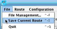 All that’s left is to test and subsequently deploy your interface. To test the interface, select Switch to Testing Mode beneath the Route menu.
  When you do this, all the icons between the Source and Target system will be replaced by question marks, indicating a stage of a test that you may or may not choose to run.
 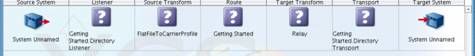 For the purposes of this exercise, let’s begin the test with the first sub-stage of the Source Transform. Do this by selecting the Source Transform icon. Then select the first substage, Delimited and Fixed-Width File Transformation Module.
  Now click the Start Test Here checkbox in the Stage Configuration area to the right.
  Green and blue arrows will appear depicting the path that the data may take when you execute this test. Now click the Execute Test button.
  Because you’re not starting with the Listener, you will be prompted to provide a sample file. A sample file was provided in the Tutorial directory. It exists in the docs folder, called ratings.dat. Select this file and click Open.
 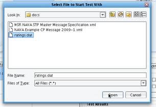 As each stage of the test completes, the question marks will turn into either a checkmark or a red X. A checkmark indicates successful execution of the stage, and an X is indicative of a failure.
  You can now choose any stage or sub-stage and view the data as it appeared when it passed out of that stage. You can begin by viewing your inbound sample data. With the Source Transform stage selected, click View under Stage Configuration.
  This is the same file that you worked with in the File Specification Editor.
  By double clicking on the Delimited and Fixed-Width file transformation module stage, you’ll see the representation of that file after it was parsed by the File Specification engine and converted into an XML format.
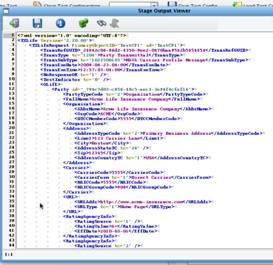
 You then executed an XSLT to map that data onto the IRI (NAVA) CarrierProfile message. Double clicking the XSLT stage will display your well formed IRI (NAVA) TXLife request.
 Having reviewed the behavior of this interface, you are now ready to deploy this interface to an XCS eiPlatform instance. If you are using the free, or evaluation version, of the XCS eiConsole you will need to license the XCS eiPlatform to deploy this interface to production. You have now successfully tested your first XCS eiConsole interface where you’ve taken a Flat File and generated an IRI (NAVA) compliant CarrierProfile message from it. You’ve learned how the IRI (NAVA) specific functionality can greatly enhance productivity and speed to market when generating transformations to or from the IRI (NAVA) formats.
  To review, you first configured the topology of your interface in the main route grid. You used the Delimited and Fixed-Width File Transformation Module along with the File Specification Editor to describe how the inbound flat file should be parsed. You then used the XCS Data Mapper to map information from the flat file format onto the IRI (NAVA) CarrierProfile message. The IRI (NAVA) format builder provided a great amount of value in allowing you to navigate IRI (NAVA) specific documentation, typecodes, etc. during the creation of this map. You finished by testing the interface in Testing Mode. The final step in working with any XCS eiConsole interface is deployment to an XCS eiPlatform server. If you are a licensee of the XCS eiPlatform server, this can be done by returning to the File Management window…
  Selecting your interface and then deploying to your server instance.
  You now know how to create interfaces are the highest-level of visible abstraction within eiconsole. any given>Interface is defined by one or more Routes. ” class=”lexicon-term”>interfaces in the XCS eiConsole using the IRI (NAVA) bundle.
https://cms.pilotfishtechnology.com 860 632 9900  PilotFish, Inc. 100 Roscommon Dr. Suite 220 Middletown, CT 06457 2001 PilotFish, Inc.