eiConsole v.25R1
Tutorial & Interface
eiConsole Tutorial Basic
Multi-Stage XML Workflow
Welcome to the eiConsole Multi-Stage XML Workflow Tutorial. Often automation of a business process requires more than simple point-to-point integration of Source and Target Systems. The eiConsole supports the implementation of a wide variety of the workflow patterns common to these more complex Business Process Modeling (BPM) scenarios. Supported patterns include sequencing, splitting, merging, branching, conditional logic, and iteration. In this tutorial, we will take you through an example of a multi-route interface that demonstrates a number of the components used to implement a multi-stage XML workflow in the eiConsole.
Place the eip-root directory from the Training Kit for this section to the desired folder on your drive. In our case, it’s
c:\Program Files\PilotFish Technology\Samples\.
Open the eip-root directory as a new Working Directory, using the Browse button.
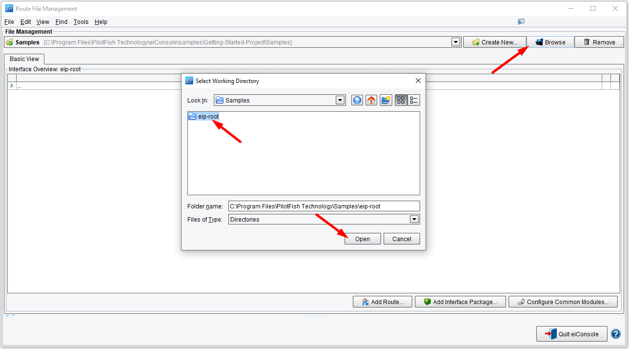
Your Route File Management window should now have 4 routes. The last 3 are marked by blue icons, which means these routes are fully configured. We want to configure the first one – to begin, double-click on it to open the eiConsole’s main route grid.

Let’s begin by talking about the different levels of modularity within an eiConsole interface. It all starts with a Stage. There are 7 stages in the eiConsole’s main route grid. Stages are things like Listeners, Transforms, Routing or Transport. These are essentially a node within a workflow, representing an action on the data. A Route, like we’re looking at here, represents a collection of these stages. These make up an XML pipeline. In the eiConsole, within a Route, data travels in one direction between a set of Source Systems and one or more defined Target Systems.

First, we need to configure the Listener. Select the Listener stage and click the icon to open the Listener Configuration panel. The Listener Type (Directory / File) is already selected, so we’ll leave that.

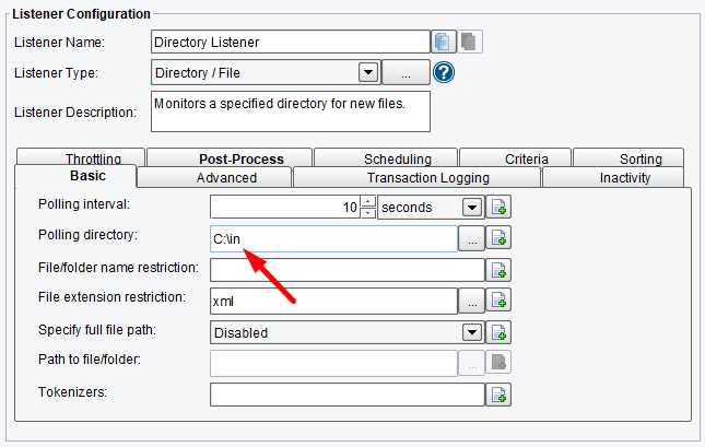
We need to point the Polling directory at the correct file on your computer. That is wherever you placed the downloaded Tutorial Workflow folder. Click the Ellipsis button to the right of Polling Directory, click and navigate to the Workflow folder, select the input folder and click Open.
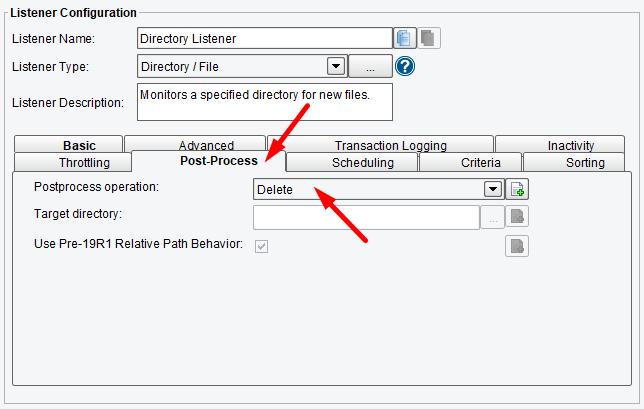
Set the Post-Process operation.
A single Route with one Source and one Target is the simplest possible example of an XML workflow in the eiConsole. However, we need two defined Target Systems in this example – one named PilotFish and one named Sharks.
We will need two. Click the Add Target button to add a second target.

The second Target System appears in the grid.

We want to name our two Target Systems, but to do so, we first have to name our two Target Transforms. So, click the Add Format button.
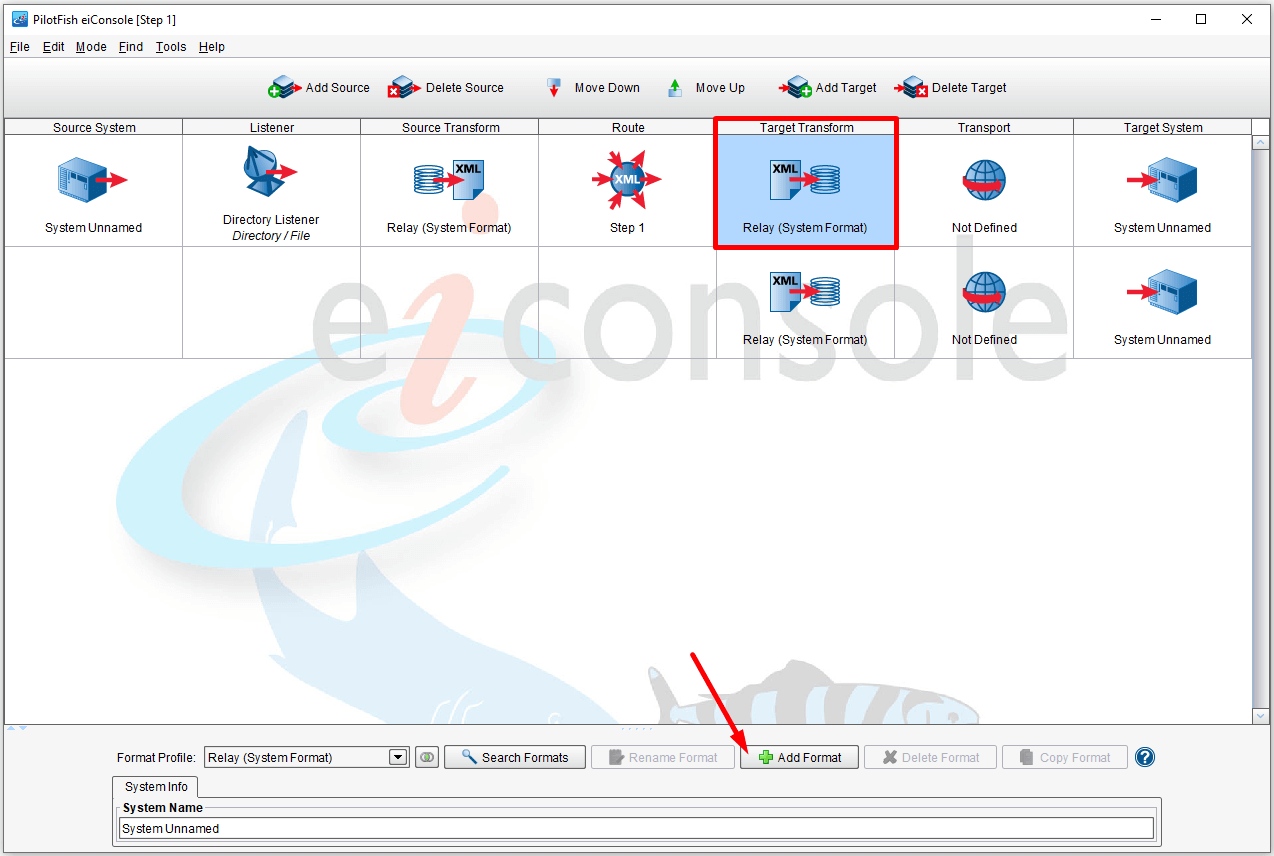
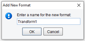
Name your first Target Transform by entering the name in the Add New Format box (in our example shown below – we entered Transform1) and click OK.
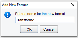
Repeat the same process for the Second Target Transform. Be sure to enter a different name (in our example shown below – we entered Transform2) and click OK.
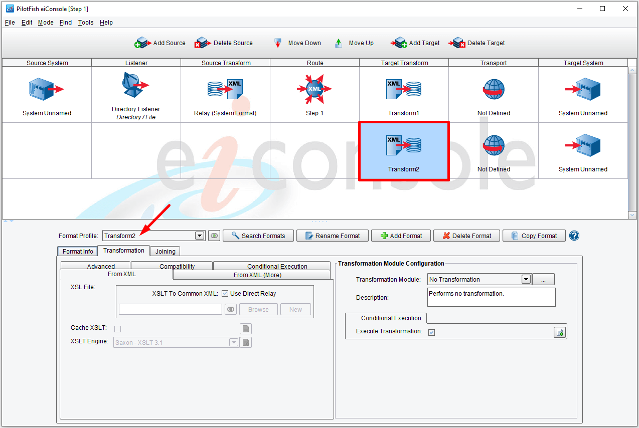
Your main route grid should resemble what is shown below. Note the names Transform 1 and Transform 2 now appear in the Target Transform column.
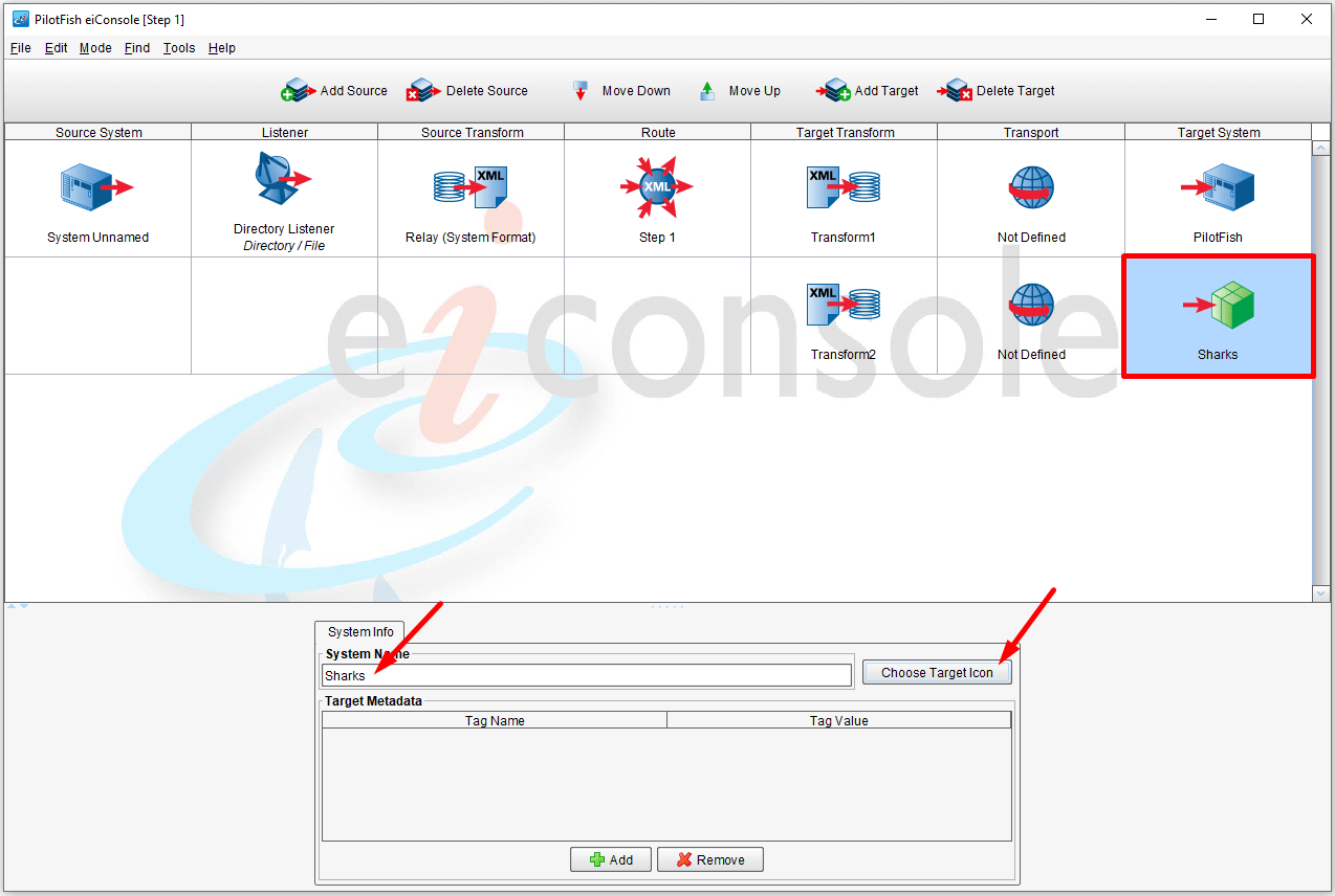
Now you can name your Target Systems. To do so, select the Target System stage and click the icon. The System Info dialogue panel will open. Enter a name in the field (in our example shown below – we entered PilotFish) and choose an icon.
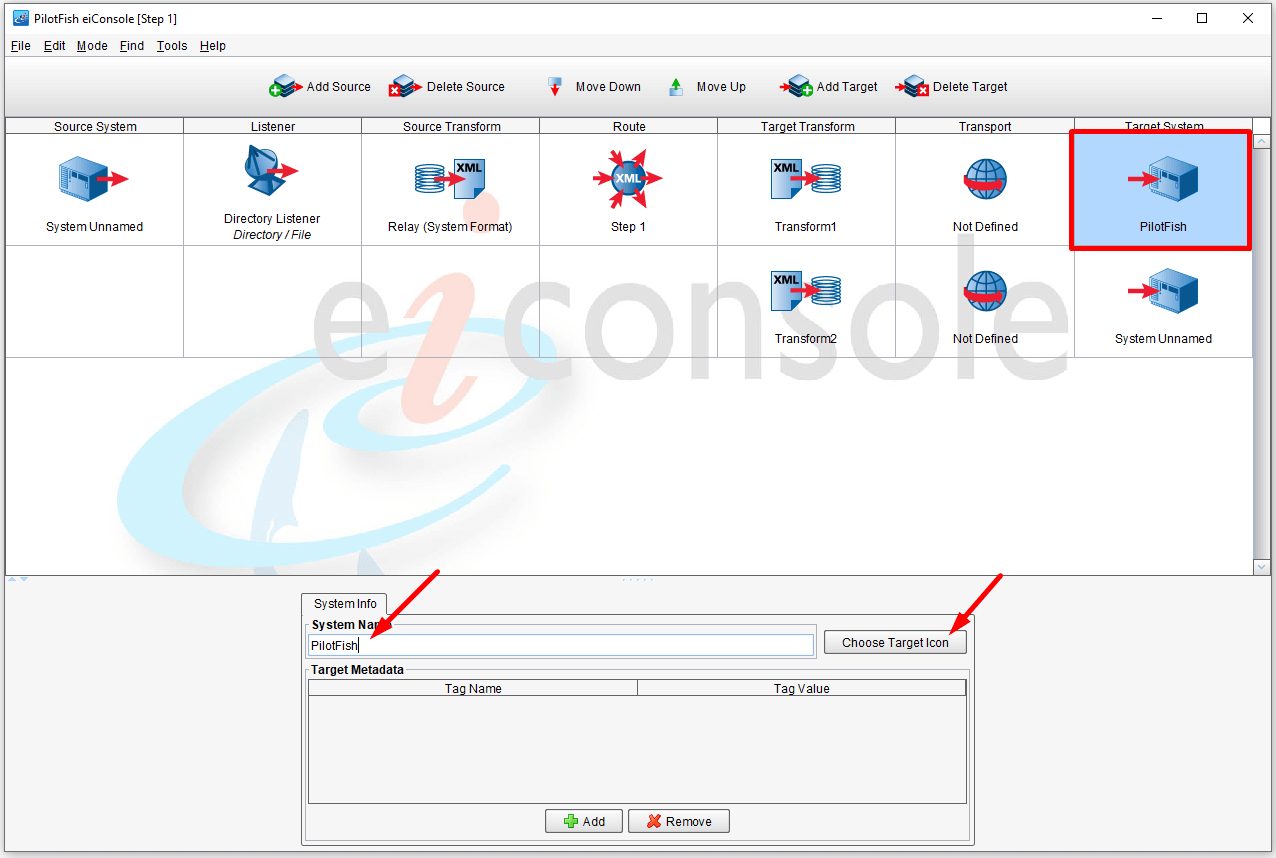
Repeat the same process with the second Target System. Name it Sharks.
Next, we need to add the Source System information. As was with naming the Target System, the first step in the process is to configure your Source Transform. Select the Source Transform stage in the grid. Click the Add Format button and enter a name in the Add New Format dialogue window. Click OK. In our example shown below – we named ours Fork.
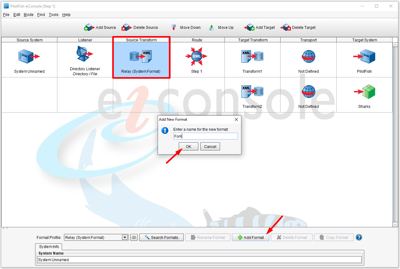
Your main route grid window should now resemble the main route grid shown below. Note: your Source Transform is now named Fork in the grid.

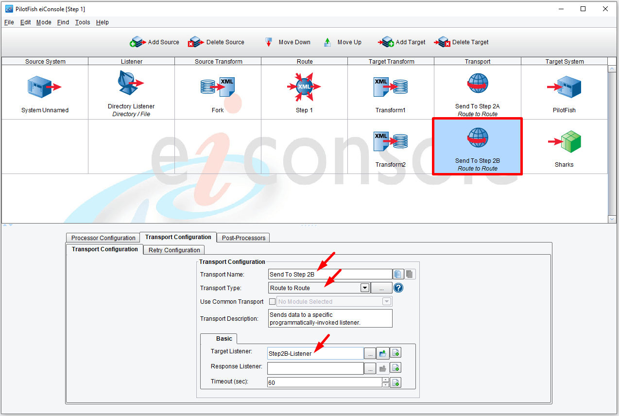
In the Transport stage, we select the RouteToRoute Transport Module. Both Targets use this same Transport Type, but they’re configured slightly differently. Unlike many of the other available connectivity options, the RouteToRoute Transport is used to sequence multiple routes within the given interface. Here we’ll see that Sharks will be passed to one Route indicated by the Listener name and PilotFish to another. In addition, you’ll see PilotFish is sent to a Listener called Step2A-Listener.
Click the first Transport icon in the main route grid to open the Transport Configuration panel. Name it Send To Step 2A. In the Basic tab, enter Step2A-Listener in the Target Listener field.

Repeat the process for the second Transport, but enter Step2B-Listener in the Target Listener field and name it Send To Step 2B.
When a Route has more than one Target, the Routing Module is used to select the appropriate execution path or paths. Here, we expect our input message to represent a Fish. If the Fish is a PilotFish, we will proceed down the top path. If the Fish is a Shark, we’ll use the second path. All other messages will be discarded. Hence, the Routing Stage can implement both conditional logic and filtering.
Select the Route icon in the main route grid. The main Route configuration panel opens to the General Tab.
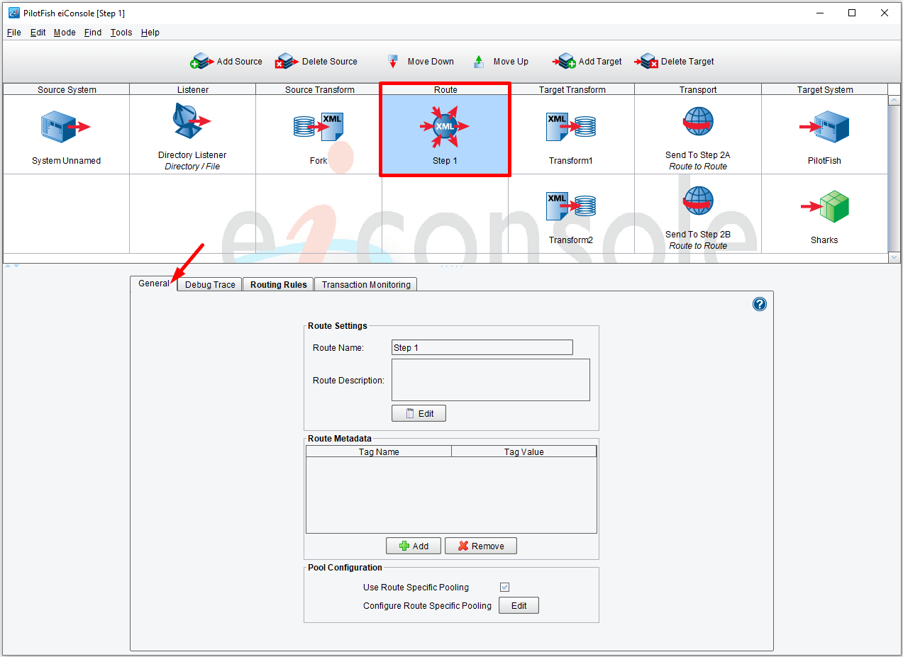
Click the Routing Rules tab to open the configuration panel.

Сlick the Add Rule button.

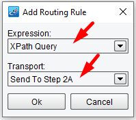
The Add Routing Rule dialog will appear. Select XPath Query for the Expression, and Send To Step 2A for the Transport (our previously configured Route). Click OK.
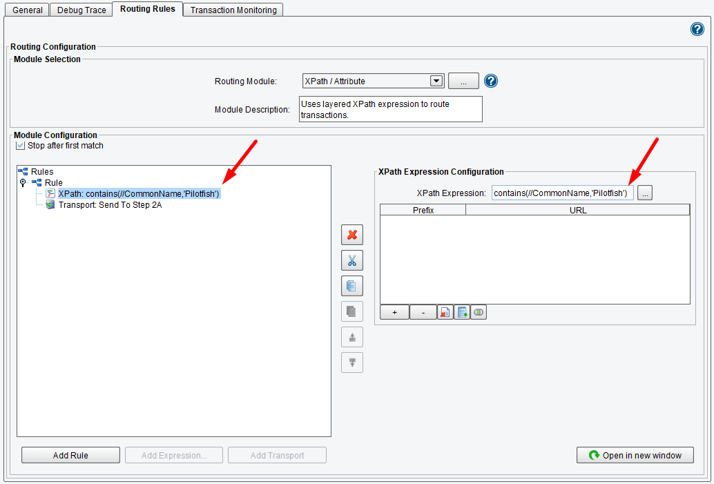
Enter a name in the XPath Expression field. In the example shown below – we entered: contains(//CommonName,'Pilotfish').
Please note that case matters: Pilotfish and PilotFish are two different names.
Click enter to save. Note the XPath expression now appears in your Module Configuration panel tree.
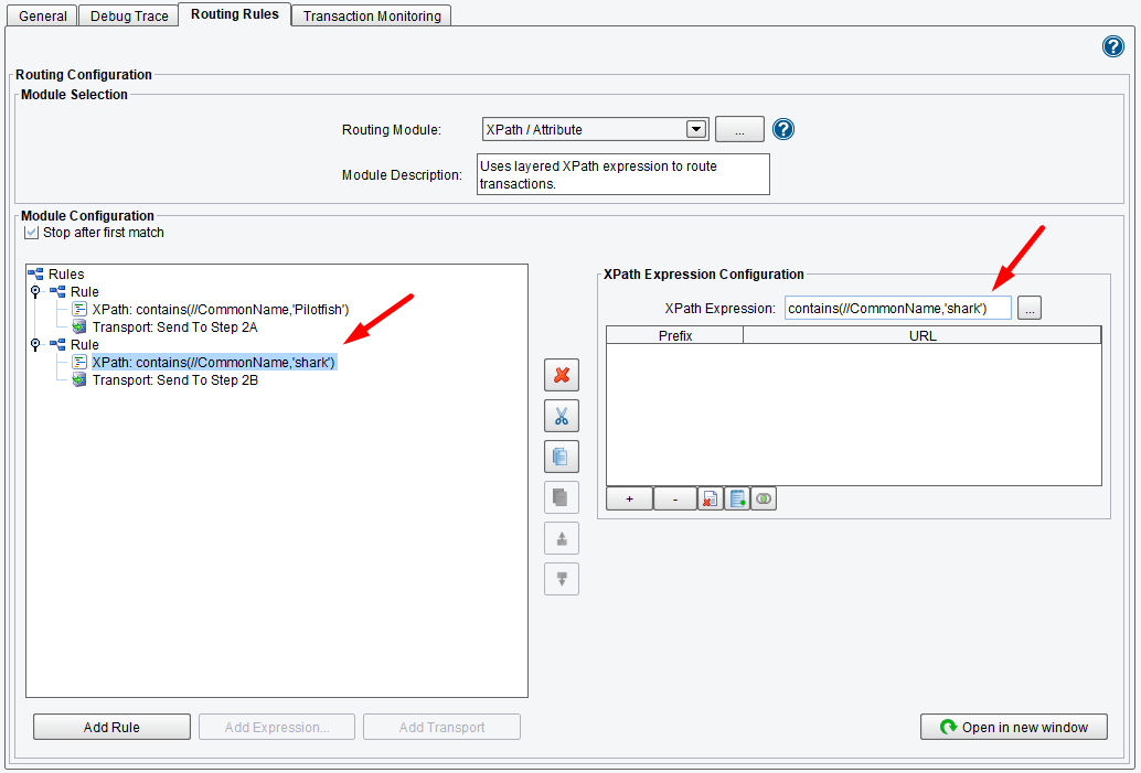
Our second rule checks to see if the CommonName is shark – contains(//CommonName,'shark'). If so, it sends it to Step 2B. Follow the same process you did for configuring the first set of rules and configure the second rule – Sharks and Step B. Once you have completed these steps, your panel should resemble the panel below.
You are ready to move on to the Source Transform. Click the Source Transform icon in the main route grid. The main Source Transform panel opens. Select the Forking tab, then select XPath Forking from the Forking Module drop-down menu.
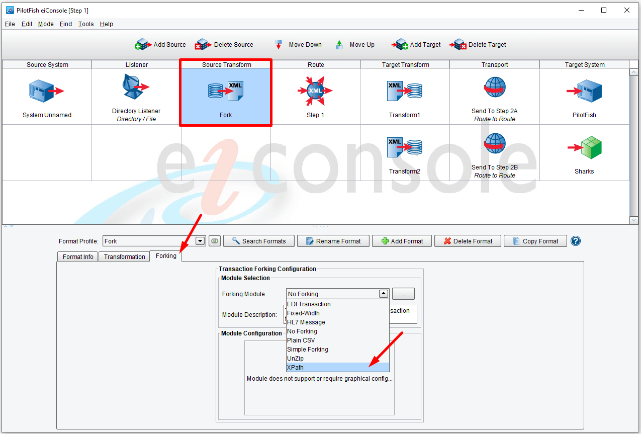
Also demonstrated in this Route is our ability to perform a parallel split or forking operation. We see this configured in the Forking tab of the Source Transform. The input document that we’ll be using for this Route is a “batch file” of Fish – each represented as an XML tag. We have used the XPath Forking Module to pull out each Fish tag and turn it into its own transaction.
We enter /FishXML/Fish in the XPath Expression field. Click enter to save.

Also, let’s name the Source System. As we start with the file from our local Workflow directory, let’s name it Local Drive. And let’s choose an icon for it.

In the Testing Mode of the eiConsole, we’ll start with the stage immediately before the Source Transformation and we’ll allow the test to run through to both defined Targets. But first, you’ll need to save your Route. To do so, go to the File menu and select Save Current Route.

Next, go to the Mode menu and select the Testing Mode.

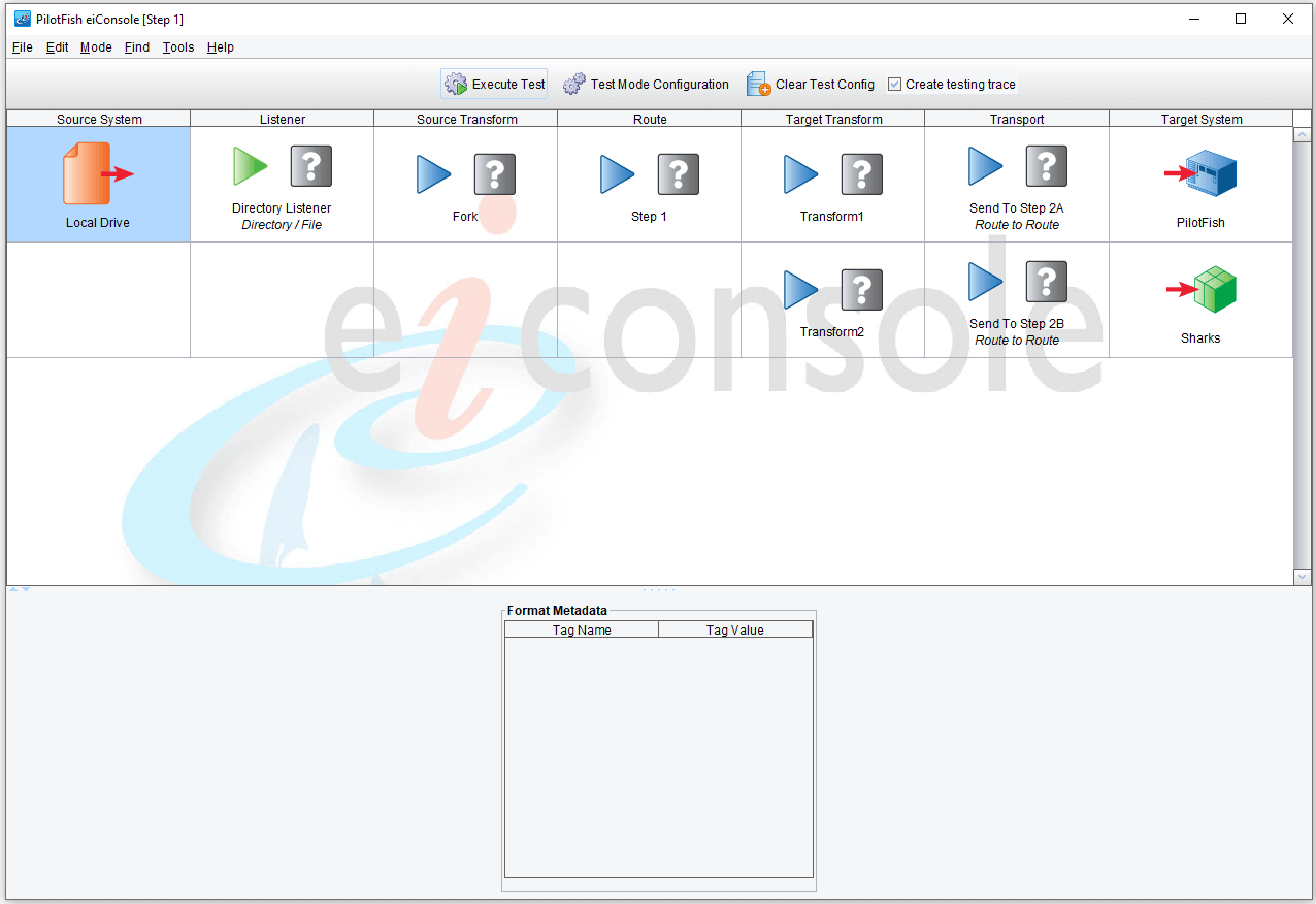
The eiConsole’s inline graphical test mode opens.
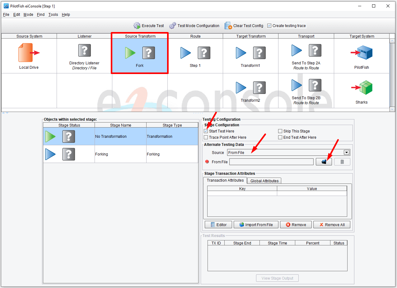
Select the Source Transform icon in the main route grid. Check the Start Test Here box in the Stage Configuration area, choose the From File in the Alternate Data Source drop-down menu. Click Browse.
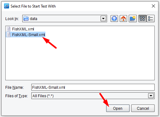
Navigate to your Workflow folder, choose your sample XML file in the Select File to Start Test With dialogue window. You’ll want to select the FishXML-Small.xml file.
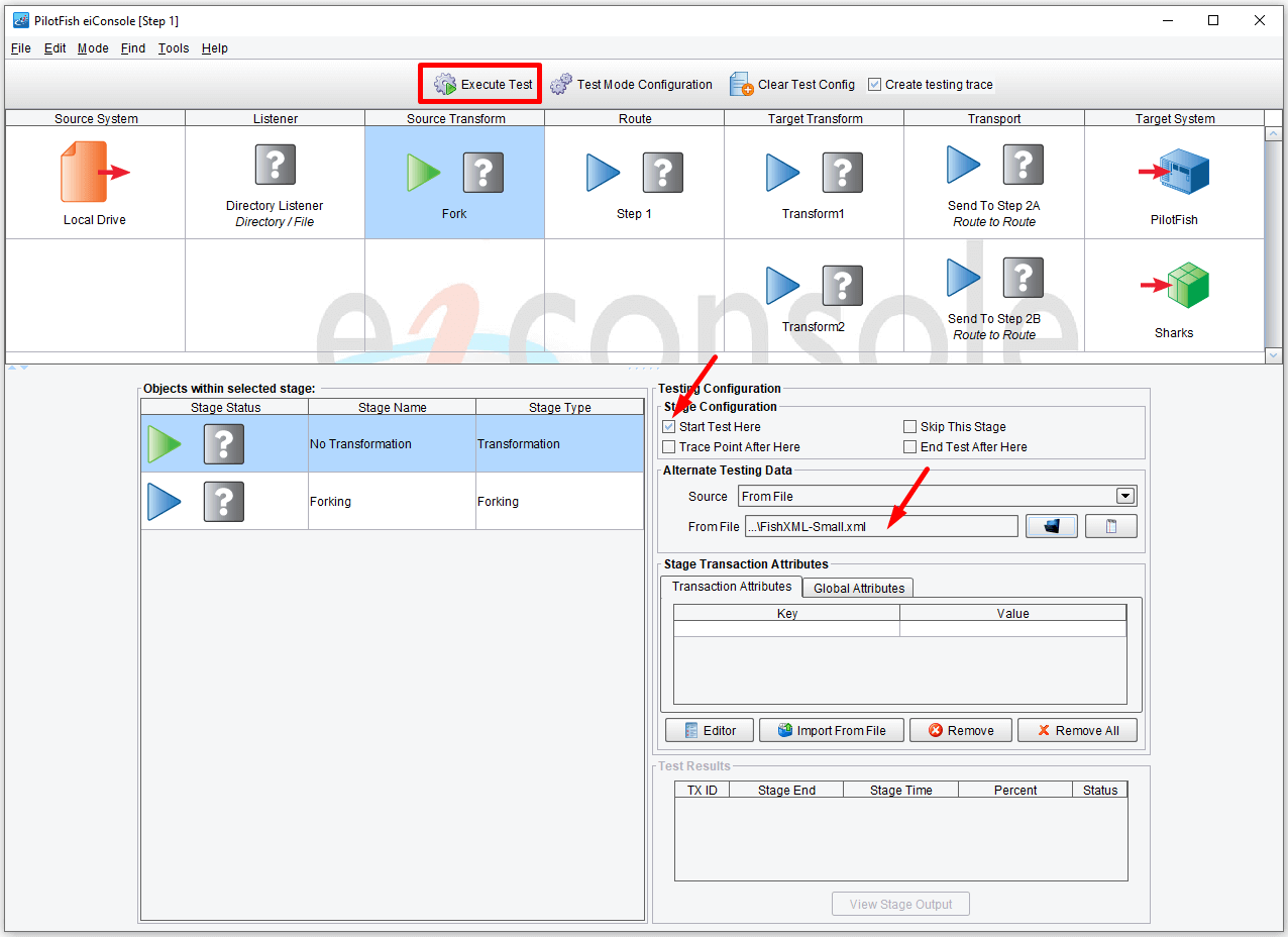
With the Source Transform Stage still selected, let the test run to the two defined targets. Then, click the Execute Test button at the top to start the test.
Once the test executes, the blue questions marks will have been replaced by green checkmarks indicating that the test has been successful. A red X would indicate a failure.
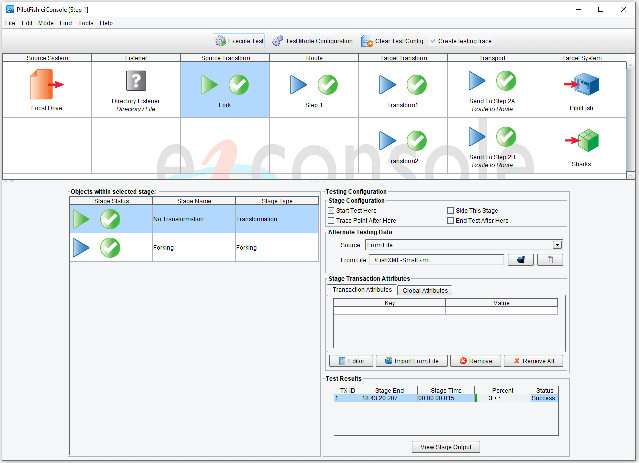
With the “No Transformation” stage still selected in the left panel, click the View Stage Output.
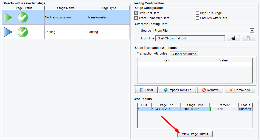
Now, let’s take a look. The input is FishXML with a number of different Fish tags.
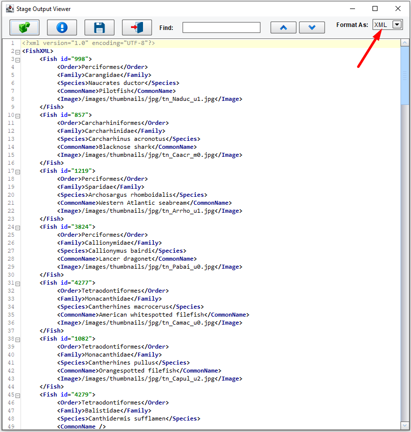
Next, select the Forking Stage, then click View Stage Output.

As you can see, the Forking stage then performed a parallel split.

Next, select the Route stage. We can see it split into a number of different transactions, each depicted as a row in this Test Results grid.
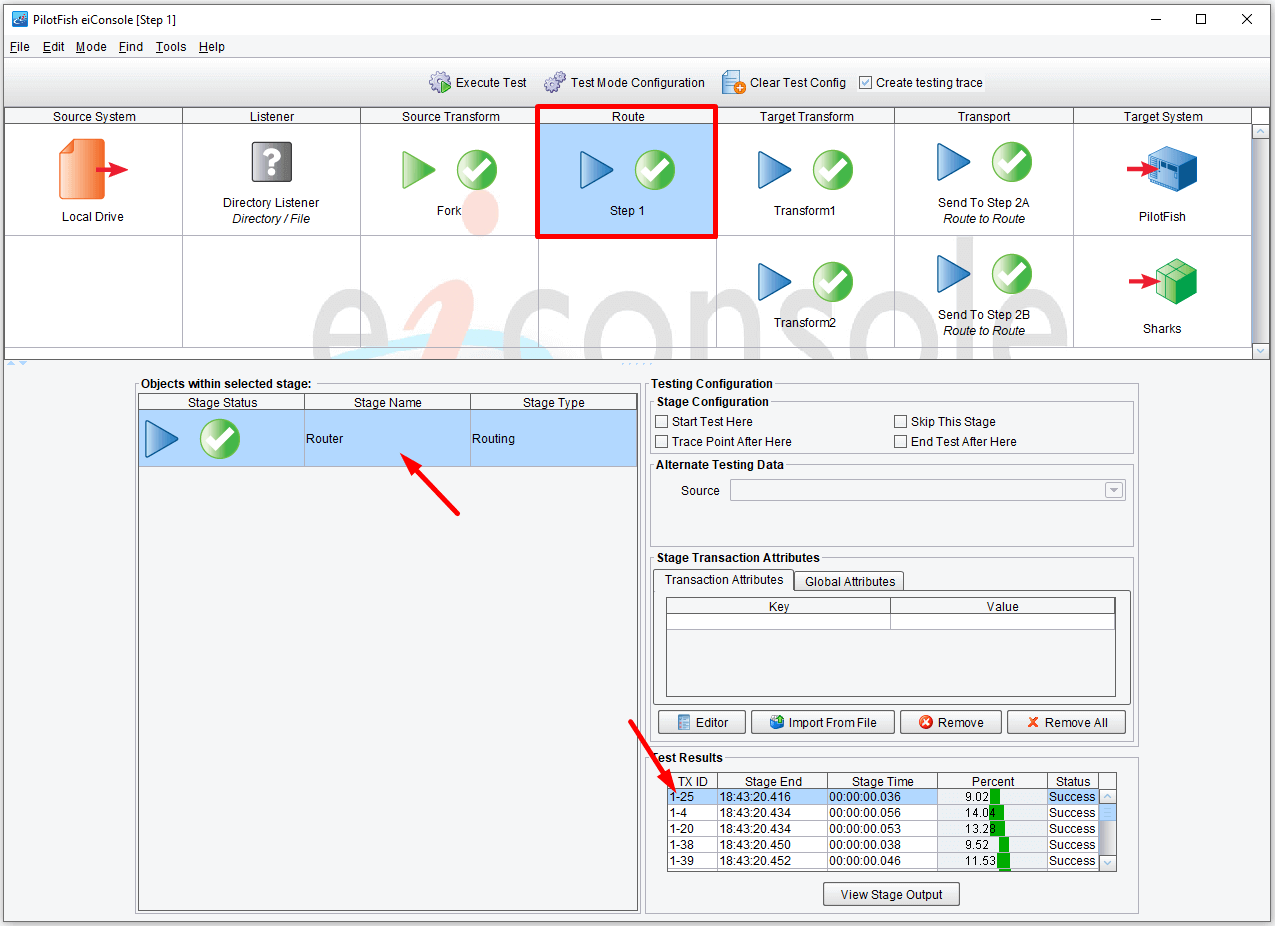
After this stage, some subset of these transactions will be filtered out; others will be branched to one of the two defined Transports. You can select each row and click View Stage Output to view each transaction. Each transaction contains a different Fish. Some will be Pilotfish, some shark.

Now we select the first Target Transform stage (Transform1) and click View Stage Output to view the first test result.
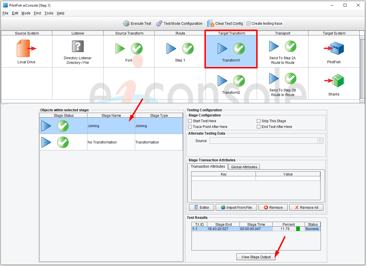
Here, we can see that one transaction was sent towards the top Transport, the Pilotfish. And we can see here that yes, it is the Fish tag that has the CommonName of Pilotfish.

We move down to the second Target Transform (Transform2), select the first row, and click View Stage Output.

We see that there were two transactions sent in the Sharks direction, one being the Blacknose shark.

Select the second row, then click View Stage Output to view the second transaction with the CommonName of Silky Shark.

Now let’s go and take a look at the next two Routes that these transactions are sent to. First, go to the File menu and select File Management to return to the Route File Management window.

You’ll see that back in our main Route File Management window; Step 1 now has the blue icon as a configured route. Next, we’ll take a look at Route Step 2A. Step 2A and Step 2B are similar.

Double click Route Step 2A to open the eiConsole main route grid. You can see that this Route is simple with a single Source and a single Target.

Select the Listener stage and click the icon to open the Listener Configuration panel.
A Programmable Listener is selected (Programmable Trigger). In the Listener Name Configuration area, we see the same text that we used in the RouteToRoute configuration area – Step2A-Listener. The name of this Listener is the link between the Transport in the previous stage and this portion of the process. This allows Step 1’s RouteToRoute Transport to call Step 2A or Step 2B by indicating the corresponding Listener’s name. Not much happens in the body of this Route until we get to the Transport Stage.

Next, select the Transport stage. We see the Transport Type selected is the Process Orchestration Transport. This robust transport component allows for the implementation of any number of synchronization and state-based workflow patterns.
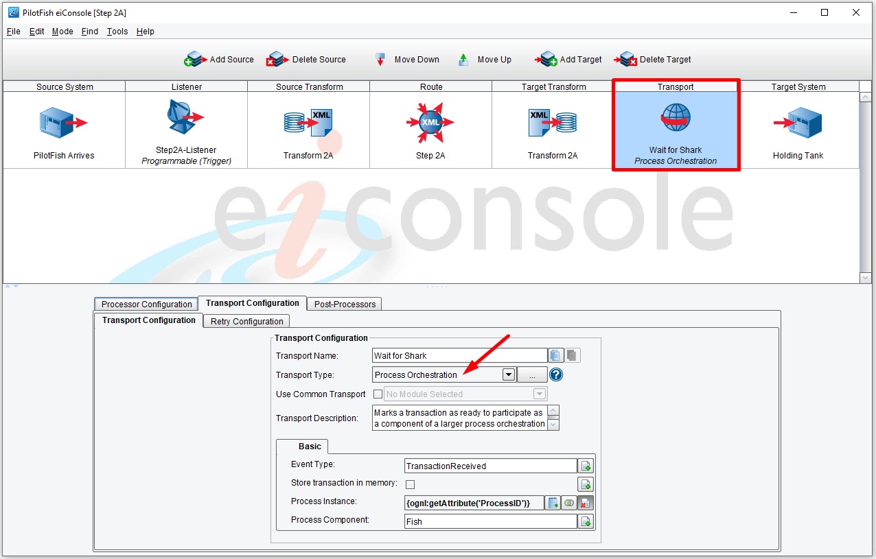
Perhaps most interestingly, the Process Orchestration Transport, and its corresponding Process Orchestration Listener, allow us to merge asynchronous transactions. In other words, it can serve as a rendezvous point for data arriving from different sources. Here, we want to rendezvous a PilotFish message with a shark message so that we can merge the two XML messages into a single XML document for further processing. The Transport indicates a process component, which is essentially the piece of this process that the current message represents. Essentially, what we’re doing is creating an empty puzzle board and specifying when a piece of that puzzle should be placed in that puzzle board. Here we’re saying, put the Process Component called “Fish” into our puzzle board.
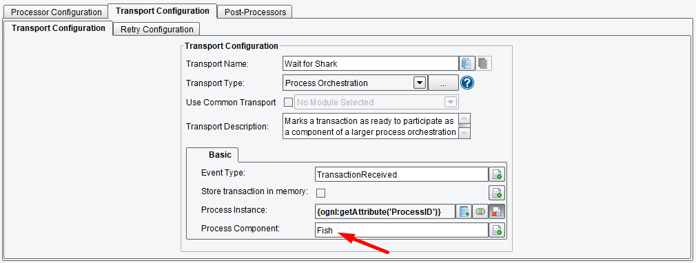
Check the Store Transaction in Memory checkbox.
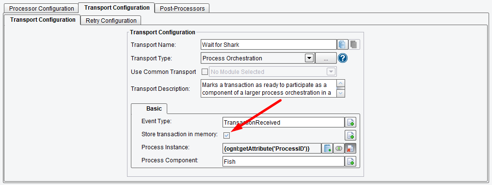
Similarly, our Step 2B Route also uses a Process Orchestration Transport, but this one places the “Shark” piece on the puzzle board.
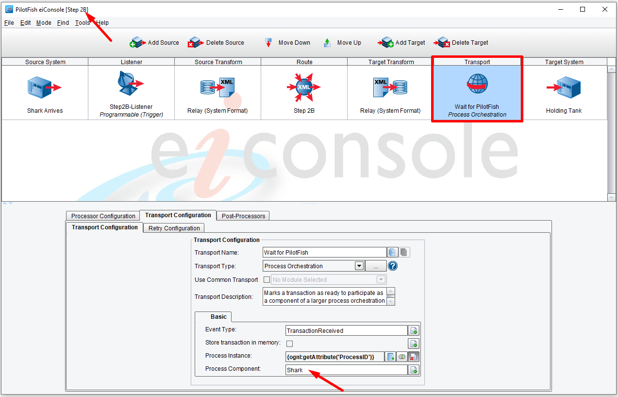
Check the Store Transaction in Memory checkbox for the Sharks as well.
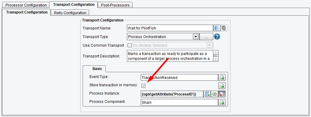
Next, we return the main Route File Management window and select our third Route. We double-click Step 3 to open the main route grid. Moving on with our third Route, we can see how we can rendezvous and merge data with the Process Orchestration Listener. We select the Listener stage. The Listener Type selected is Process Orchestration.
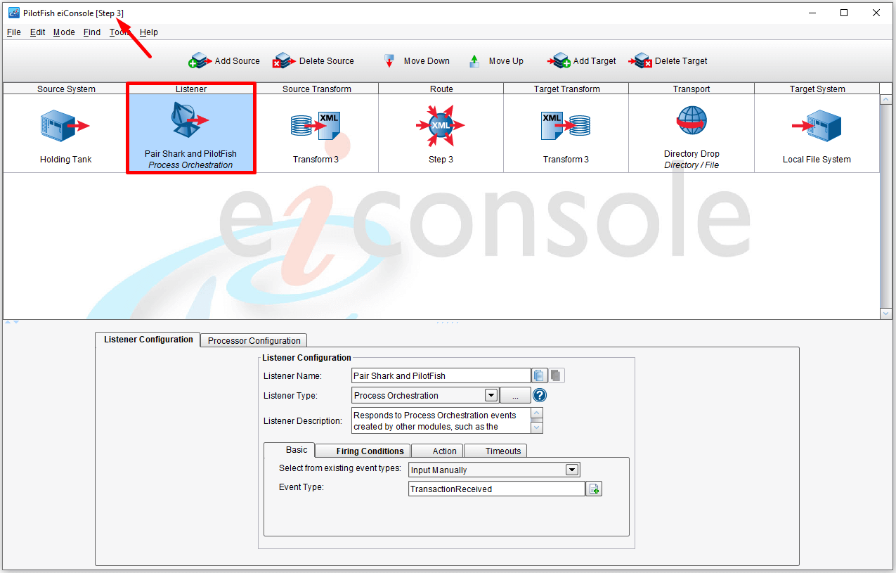
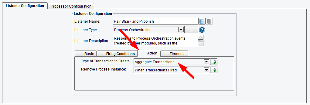
Now, here we see that under the Action tab, we’re going to Aggregate Transactions. In the Remove Process Instance field, we want When Transactions Fired to be selected.
And under our Firing Conditions tab, we’re going to do that when the Fish and Shark puzzle pieces or Process Components have arrived.
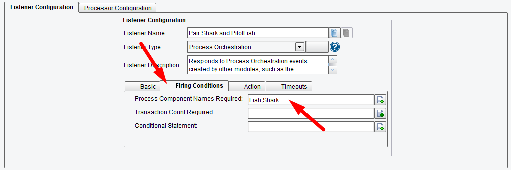
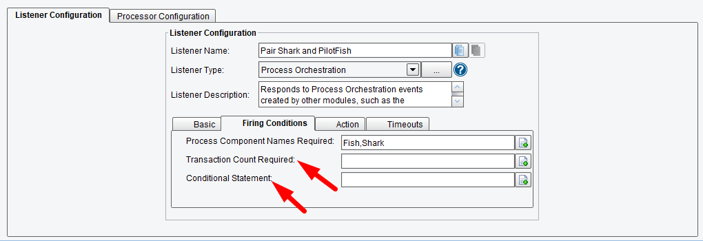
Please note that there are a number of other workflow patterns that are enabled by the other configuration options of the Process Orchestration Listener and Transport pair. For instance, we can deal with multiple transactions of the same type based on a count using this Transaction Count Required. Or we can implement conditional firing or statement-based operations with this Conditional Statement option.
But in this case, we take the data from these two puzzle pieces, combine it and then pass it through the process until we get to a simple Directory Drop Transport. Note: We want the Target file extension to be XML.

Now that we’ve walked through the 4 Routes that make up this three-step process, let’s look at this end-to-end in the Local eiPlatform Emulator. First, we go to the Tool menu to select and launch the Emulator.

But before we can run through the whole test, we’ll need to drop a file into the appropriate input directory. From our Tutorial Workflow folder, open the data folder and copy the FishXML-small.xml file. Just keep it cached for now.
We are ready to start the test. Click Start Emulator.
While it starts running, drop the FishXML-small.xml file into the input folder. Note: If any error occurs, it will be indicated by the red error message, as shown below.
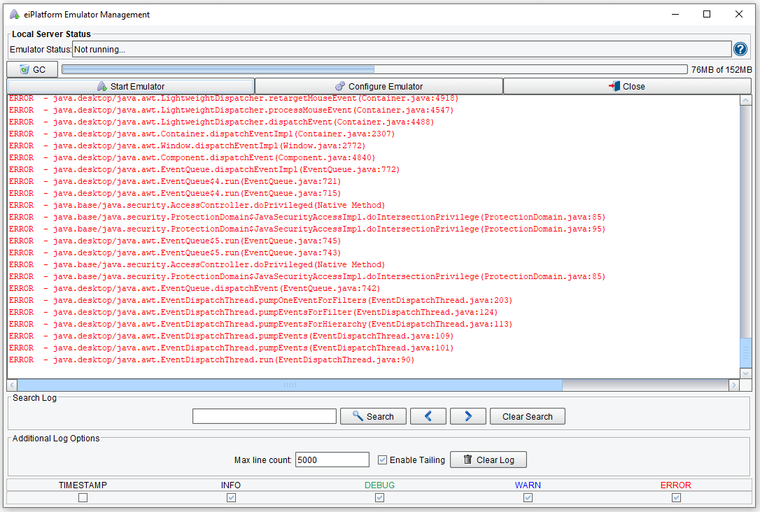
We’ll paste our batch file of Fish into the input directory and we’ll see it disappear as it begins processing.

Once we drop the file in the Emulator, it gets happy again and processes away with pleasant green transactions zipping along. All is well.
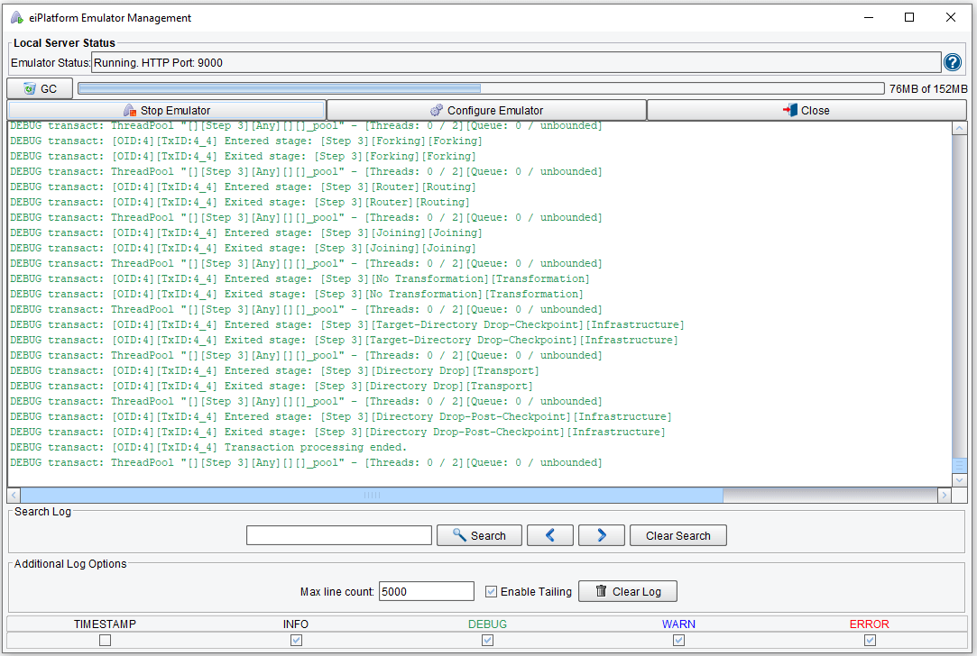
Finally, when processing completes, we’ll see our output file consisting of the rendezvoused Fish and Sharks.
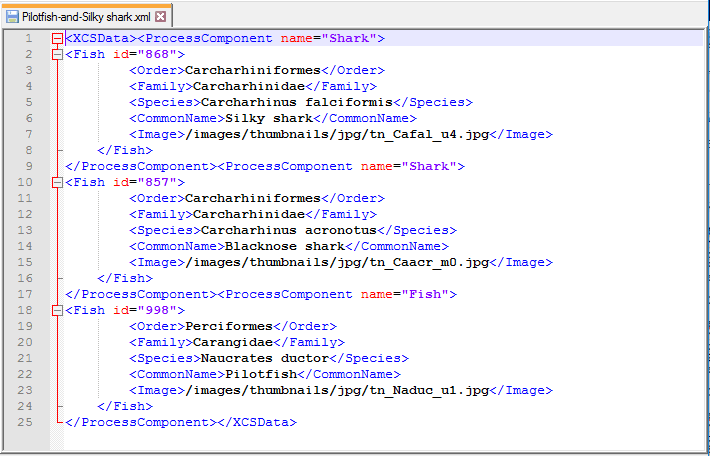
This concludes the Tutorial of Multi-Part XML Workflow handling within the eiConsole. To review, we’ve seen how an eiConsole interface can be made up of stages and routes and how various workflow patterns can be implemented with forking, process orchestration, and routing rules. With the eiConsole, you have powerful tools at your fingertips that can support workflow patterns common to more complex Business Process Modeling (BPM) scenarios.
